Network
Introduction to networks used by private cloud virtual machines and physical machines.
Basic Concepts
There are three basic network concepts, in logical order from bottom to top, they are VPC, layer 2 network and IP subnet.
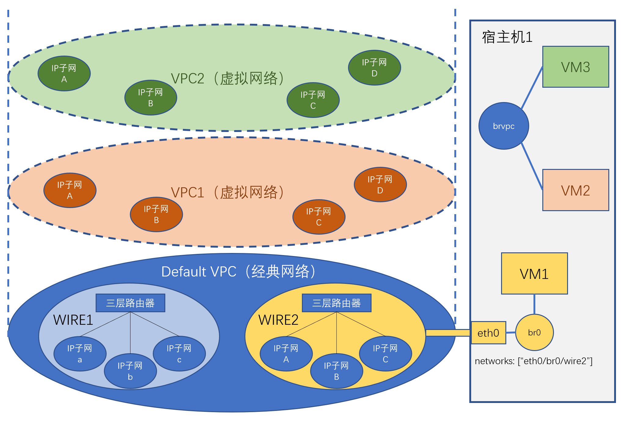
VPC
VPC (Virtual Private Cloud) refers to a virtual network isolation area within the cloud platform. Network traffic between VPCs is isolated. VPCs are further divided into classic networks and virtual networks.
Classic Network
Classic network is also called flat network or Underlay. It refers to the physical network defined by physical switches, routers and network configurations within these physical devices. Virtual machines using classic networks rely on physical network devices to implement network communication between nodes. Communication between virtual machines under the same IP subnet relies on layer 2 switching. Communication between virtual machines under different IP subnets relies on layer 3 switching. In classic networks, layer 2 or layer 3 network switching between virtual machines located on different hosts, or layer 3 network switching between any virtual machines, all need to rely on physical network devices.
For unification, classic network is defined as a special default VPC (Default VPC). This VPC exists by default and represents the network isolation area corresponding to the physical network.
Virtual Network
Virtual network is also called Overlay network. It is a virtual network composed of virtual network elements interconnected through tunnel technology (tunnel) built on physical networks. Virtual machines within virtual networks communicate through software-simulated virtual layer 2 switches and virtual routers (layer 3). You can create any number of virtual networks. Traffic between virtual networks is isolated.
Virtual networks are implemented based on open source ovn encapsulation.
Layer 2 Network (wire)
In classic networks, a layer 2 network corresponds to a broadcast domain. Virtual machines in the same layer 2 network can directly communicate point-to-point without relying on layer 3 network device switching (but rely on layer 2 network devices, which may be virtual ovs bridges or physical switches). Physically, a layer 2 network usually corresponds to a network area under a layer 3 switch or router. There can be multiple layer 2 networks in classic networks.
In virtual networks, since any devices can directly communicate (through tunnels), it can be understood that the entire VPC is a layer 2 network. For model unification, the concept of layer 2 network is still retained in virtual networks, but wire and VPC can be considered equivalent. A layer 2 network will be created by default within a virtual network VPC.
IP Subnet (network)
IP subnet corresponds to a subnet, which is a continuous IP address segment with the same subnet mask. IP subnets belong to layer 2 networks. IP subnets carry network configuration information, such as IP address range, subnet mask, gateway, VLAN ID, DNS, etc. If a virtual machine is connected to an IP subnet, the virtual machine's virtual network card must use an IP address allocated from the network segment of this IP subnet. The virtual network card's configuration is determined by this IP subnet's attributes.
In classic networks, each IP subnet can have its own VLAN ID. Virtual machines connected to this IP subnet must also use the corresponding VLAN ID.
Network Topology Constraints
In classic networks, because communication between virtual machines relies on physical devices, which IP subnets virtual machines on specific hosts can access are constrained by the physical networks that hosts are connected to. That is, virtual machines on a host can only access IP subnets within the layer 2 networks that the host is connected to.
Virtual networks do not have network topology constraints. That is, any virtual machine on any host can access any VPC network.
📄️ Host Network
Networks of hosts where private cloud virtual machines are located.
📄️ Bare Metal Network
Currently, bare metal servers can only use classic networks.
🗃️ VPC Network
6 items
📄️ Typical Network Configuration
This article introduces several typical private cloud network configurations
📄️ Virtual Machine Domain Name Settings
Virtual machine domain names involve the following services:
📄️ Change Host Network Card's Connected Layer 2 Network
Introduction to how to change the layer 2 network that the platform host network card is connected to.
📄️ Add Host Network
Applicable when the deployment environment uses gigabit networks, and later extended environment deploys 10-gigabit network bonding, etc.
📄️ Virtual Machine Network Card Multi-Queue
The platform supports enabling multi-queue features for virtual machine virtual network cards.
📄️ Network Parameter Configuration
This section introduces private cloud virtual machine network settings, including DHCP, DNS, NTP and other settings.
📄️ Traffic Mirroring
Introduction to traffic mirroring concepts and operations.
📄️ Network Card Traffic Limit
This section introduces setting network card traffic limits. Network card traffic limits are divided into upstream and downstream traffic. As long as traffic on one side exceeds the limit, the network card will be cut off. Network card traffic limits are implemented by collecting network card receive and send packet monitoring data. The collection cycle is one minute, so traffic may exceed the limit but the network card will only be cut off after the traffic collection cycle arrives.
📄️ IP Reservation
Introduction to IP address reservation functionality.
📄️ Network Card Subordinate IPs (SubIPs)
By default, a virtual machine's virtual network card can only be allocated one IP, but you can allocate several subordinate IPs to a network card through the following method. The platform checks the source IP of virtual machine network card traffic by default. Through subordinate IPs, you can allow using multiple IPs within the virtual machine.
🗃️ SSH Proxy Service
2 items